How to Select a PCB Connector by Pitch, Current, and Locking
Choosing a PCB connector is usually one of the last steps in a board design, but it is often one of the first components to fail in the field. A connector that is undersized for current, mismatched to the wire gauge, or loose under vibration shows up later as intermittent contact, overheated terminals, or customer returns. Three specifications carry most of the decision weight: pitch, current rating, and locking type. Get these three right and the rest of the selection falls into place.
This guide covers each parameter from an engineering perspective and uses specific reference parts to show how each specification translates into a practical choice.
Board-to-Board vs. Wire-to-Board: Define the Interface First
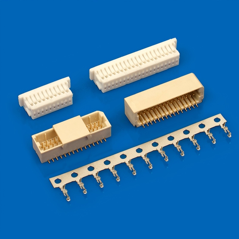
Start with a different question: what is this connector connecting?
What are Board-to-board (BTB) connectors
Board-to-board (BTB) connectors join two PCBs directly, usually in a stacked or mezzanine arrangement inside one enclosure. The interface is rigid, the signal path is short, and there are no loose cables to manage. BTB parts fit display modules, sensor boards, and stacked power boards. The B1251 series is a 1.25 mm pitch example in this category: a Nylon 66 housing, 0.8 A max rating at 125 V, and a 32 to 28 AWG wire range.
What are Wire-to-board (WTB) connectors
Wire-to-board (WTB) connectors terminate discrete wires, so they must handle crimp termination, strain relief, and the mechanical abuse a cable assembly receives in service. If a cable leaves the enclosure, plan for a wire-to-board connector. For fine-pitch wiring, the A1001-H05 is a 1.0 mm pitch wire-to-board connector rated at 1 A and 50 V. For heavier cabling, the C6203-H02 is a 6.2 mm pitch wire-to-board connector rated at 5 A and 300 V with an 18 to 14 AWG wire range.
Pitch: Density vs. Current Capacity
Pitch is the distance between contact centers, and it sets the character of the connector family. Smaller pitch means more contacts per unit of board edge, attractive for dense, signal-heavy designs. Larger pitch means more room for current, thicker wire, and a more forgiving assembly process.
When to Choose Small Pitch (1.0 to 1.25 mm)
Small pitch buys board area and pin density. A 1.0 mm wire-to-board connector like the A1001-H05 fits high I/O counts on a compact board when the enclosure is the constraint. The same logic applies to the 1.25 mm B1251 series for stacking.
The trade-off is current and wire size: small pitch connectors typically carry 1 A or less per contact, accept fine wire in the 28 to 32 AWG range, and suit signals, not power.
When to Choose Large Pitch (2.0 to 6.2 mm)
Large pitch trades board area for current capacity, wire size, and tolerance. A 6.2 mm wire-to-board connector such as the C6203-H02 carries 5 A per contact at 300 V and accepts 18 to 14 AWG wire, for power distribution, motors, and heating loads. Wider spacing also leaves more room for crimp tooling and solder inspection.
For mixed signal and power, a middle pitch such as the B2003 series sits between the two extremes: a reasonable footprint with more current than a 1.0 mm part.
Current Rating and Contact Area
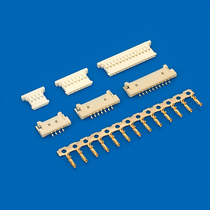
Current rating is a thermal limit, not a marketing number. Current through a mated contact pair generates heat in proportion to the contact resistance, which is driven by the metal-to-metal contact area. Less contact area means more resistance, more heat, and a lower safe current.
Three practical points:
- Design to about 80% of rated current for continuous loads, since ratings assume a defined ambient temperature.
- Match the wire gauge to the contact. The wire must carry the same current without acting as a fuse; a 16 AWG wire does not belong in a 28 AWG contact.
- Check voltage with clearance in mind. Higher voltage ratings, such as 300 V on the C6203-H02, come with wider pitch and longer creepage paths.
The table below summarizes the reference parts discussed in this article.
| Series | Pitch | Interface | Max Current | Max Voltage | Wire Range | Operating Temp |
| A1001-H05 | 1.0 mm | Wire-to-board | 1 A* | 50 V* | Fine gauge | -25 to 105°C |
| B1251-H02 | 1.25 mm | Board-to-board | 0.8 A | 125 V | 32-28 AWG | -25 to 105°C |
| C6203-H02 | 6.2 mm | Wire-to-board | 5 A | 300 V | 18-14 AWG | -25 to 105°C |
*A1001-H05 figures are reference values for the 1.0 mm class. Confirm exact ratings on the product datasheet before finalizing.
All three series share a -25 to 105°C operating range. If the application runs hotter or colder, tell the supplier early.
Locking Type: Friction, Latch, and Ear Styles
Locking type decides how the connector stays mated when the product is dropped, shaken, or pulled on. There are three common families.
Friction Lock
A friction lock relies on the interference between the housing and the header to hold the connection. It is the simplest and lowest-cost option, and easy to mate and unmate by hand. The catch is retention: friction alone suits only low-vibration, low-pull applications such as test fixtures and bench equipment.
Latch / Snap-In
A latch adds a spring arm that clicks over a shoulder on the header. The retention force is noticeably higher than friction alone, and the click confirms full seating in automated assembly. Latch styles suit mid-vibration applications: appliances, office equipment, and interior automotive electronics.
Ear Type / Locking Ears
Ear-style locking uses molded ears on the housing that hook over the header flanges. It is the strongest of the three styles and the standard answer for high-vibration environments: power tools, pumps, and outdoor equipment. When in doubt about vibration levels, choose a positive locking type. An unseated or shaken-loose connector becomes a field return, and a few cents of locking feature is cheaper than a warranty claim.
Board Thickness and Pad Layout
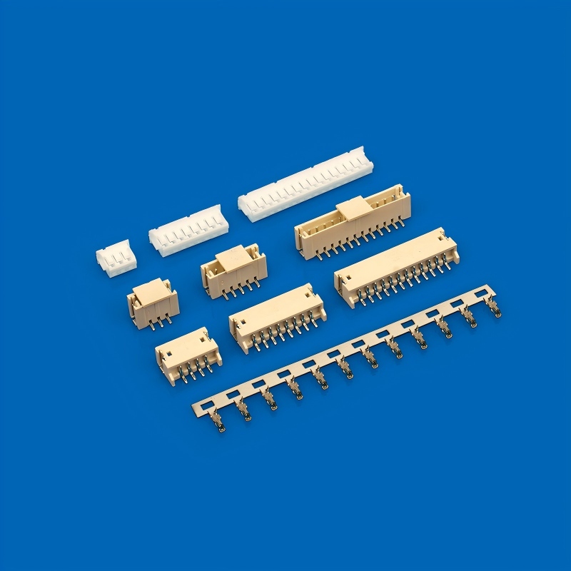
The connector does not end at the contact; the PCB must support it. A few layout rules keep the mechanical side sound.
- Match the board thickness to the mounting style. Through-hole connectors need enough barrel length for a reliable solder fillet, typically on boards from 1.0 to 1.6 mm thick. SMT versions are more forgiving but depend on pad design.
- Follow the manufacturer pad and land pattern. Pitch and contact geometry define the layout, and improvising changes solder joint stress, especially on fine-pitch parts such as 1.0 mm connectors.
- Add mechanical support for heavy parts. A 6.2 mm connector carrying thick wire can act as a lever on the solder joint. Board locks, mounting pegs, or strain relief on the cable side protect the joints from bending loads.
- Respect keep-out zones around the connector for crimp tooling and mating clearance. Check the mating height against the enclosure lid before the layout is finalized.
Frequently Asked Questions
A 1.0 mm or 1.25 mm connector rated at 1 A is too small for continuous 2 A. Move to a larger pitch or use multiple parallel contacts, and verify the derated rating against the actual load.
Short overloads are sometimes tolerable, but the rating is a thermal limit tied to contact area and ambient temperature. Repeated or prolonged overload accelerates contact wear and can anneal the spring. Design at or below the rating.
A friction lock holds the connection by housing interference only, while a latch uses a spring arm that clicks over a shoulder for positive retention. Latch and ear-style locks are the right choice for vibration and cable pull.
The reference parts in this article are rated for -25 to 105°C. For wider temperature ranges, discuss housing material and plating options with the supplier’s engineering team.
Use wire-to-board when one end is a cable that moves or gets serviced. Use board-to-board when both ends are fixed PCBAs.
Request samples and current datasheets from the manufacturer’s website or sales team. Datasheet values, especially for the A1001 1.0 mm class, should be confirmed against the latest revision.
Get OEM and ODM Connector Support for Your Board
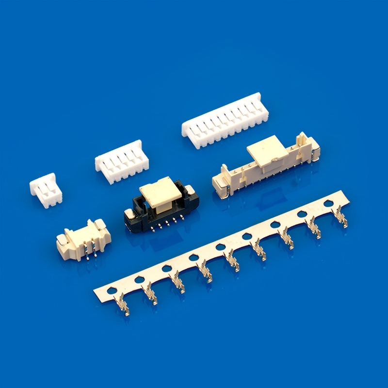
Pitch, current, and locking type narrow the choice, but production reality adds more variables: plating, housing color, custom wire lengths, and packaging. OEM and ODM connector programs cover these options with custom tooling, packaging, and documentation.
Contact us for samples and datasheets. Browse more connector options on our connector product category page.