Why the Crimp vs Solder Question Matters
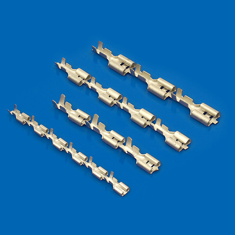
The termination method you pick drives more than the joint itself. It decides which crimp terminals, tooling, and operator training you buy, and it sets the failure mode you will see in the field. A harness with thousands of joints fails at its weakest one, so the method has to be repeatable across every joint.
Cost follows the same path. Crimping is a cold process that runs on presses and automatic machines. Soldering adds solder, flux, fume extraction, and skilled labor to every joint. For a shop running hundreds of units per day, that difference is a real line item.
Crimp vs Solder: The Core Differences
| Property | Crimp | Solder |
| Joint formation | Cold weld; barrel compressed around the strands | Metallurgical bond with filler metal |
| Vibration resistance | High; no stiff transition zone | Low; cracks at the solder wick boundary |
| Heat exposure | None at the joint | Iron heat can shrink or melt nearby insulation |
| Automation | High; presses run thousands of joints per hour | Low; mostly manual and slow |
| Repeatability | High when crimp height is controlled | Depends on operator skill |
| Inspection | Crimp height, pull force, cross-section | Visual, plus X-ray for hidden joints |
| Skill required | Moderate after setup | High for consistent results |
Mechanical Strength and Vibration Resistance
A properly set crimp is a cold weld. The barrel deforms under pressure and the strands cold-weld to the terminal metal, so the joint can match the strength of the wire itself. In a pull test, the wire breaks outside the crimp, not inside it.
Solder behaves differently. The joint is strong in tension but brittle under cyclic load, and the bigger problem is wicking. Molten solder climbs the strands and stiffens that section, so flexing concentrates at the boundary between soldered and unsoldered wire. That boundary is where vibration fractures start, the classic field failure on soldered harnesses.
This is why automotive OEM harnesses are crimped almost exclusively. Engine compartments vibrate and see constant temperature cycling. A soldered joint there is a scheduled failure.
Production Efficiency and Repeatability
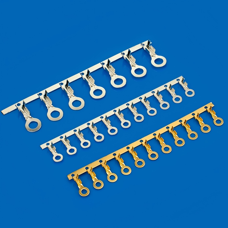
Crimp presses and automatic machines hold one die set and repeat the same force and height on every cycle. Once the setup is right, quality stops depending on the person at the bench.
Soldering is manual work with a variable outcome. Hand-fed solder, iron temperature, and dwell time change between operators. Inspection catches some of it, but rework is expensive.
Heat Exposure and Insulation Damage
Crimping is a cold process, so thin-wall insulation and nearby seals stay untouched.
Soldering irons run hot enough to shrink or melt insulation that sits close to the joint. Heat also travels up the strands and degrades the jacket beyond the immediate area. On harnesses with tight bend radii or sealed connectors, that damage is a real defect.
When to Use Crimp Terminals in Wire Harnesses
Automotive and Other High-Vibration Applications
If the harness goes into a vehicle, an off-road machine, or any equipment that runs with constant vibration, crimp. A modern car carries thousands of crimped joints, and the same logic applies to industrial and agricultural equipment.
High-Volume Production and Automation
When your line turns out hundreds of harnesses per shift, crimping is the only method that scales. Terminal strip feeders, semi-automatic presses, and fully automatic crimping machines keep per-joint cost low and quality flat. The same female crimp terminals feed through the machine at consistent tension, removing a whole class of operator errors.
When Soldering Is Still the Better Call
Prototypes, Rework, and Small Batches
If you need ten pieces to validate a design and you do not want to buy dies and a crimp tool for a run that size, solder. Setup cost is nearly zero, and you can rework a bad joint by reheating it.
Repair Work and Field Service
When a technician re-terminates a damaged wire on site, an iron and a roll of solder fit in a service bag. Crimping in the field requires the right terminal, die, and calibrated tool for every wire gauge. Solder also works for pigtails and ground straps where the joint is short and static.
How to Control Crimp Quality
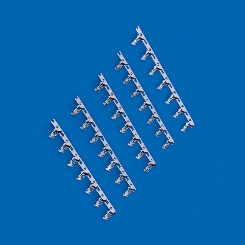
Crimp Height and Crimp Profile
Crimp height is the distance across the compressed barrel, and it is the single most useful number on a crimp line. Terminal datasheets publish a target height and a tolerance band for each wire gauge. Measure it with a micrometer or crimp height gauge and record it per batch.
Too high means the barrel grips the wire too loosely and the joint pulls out. Too low means the strands are crushed, and the joint turns weak and brittle. The right answer comes from the datasheet, not from cranking the press harder.
A matched die set is part of that. Use a die rated for the terminal family and the wire gauge, and use a ratcheting crimp tool that cannot open before the full cycle completes. Hand tools and bench presses for production use are available, starting with the wire terminal crimper range.
Pull Force Testing and Visual Inspection
Pull testing is the acceptance test for crimped joints. Standards such as UL 486A-486B and IPC/WHMA-A-620 define minimum pull-out forces for each wire gauge. In a passing test, the wire breaks outside the crimp, not at the barrel.
Microscope inspection catches the rest. A cross-section of the crimp should show strands distributed around the barrel with no missing wires and no insulation trapped inside the crimp zone. Stripping length matters here: too long leaves bare wire exposed, too short pulls insulation into the barrel, which looks fine and carries almost no current.
Common Crimping Mistakes on the Line
- Using the wrong die or a die for a different terminal family. Dies are not interchangeable.
- Overcrimping. More force is not better; crushed strands fail under vibration.
- Undercrimping. The wire slides out or pulls out at low force.
- Wrong stripping length. Bare wire past the barrel risks shorts; insulation in the barrel adds resistance.
- Partial insertion. The wire must sit fully inside the barrel before the die closes.
- Mixing gauges. A 28 AWG wire in a terminal sized for 22 AWG will not deform correctly.
- Worn tooling. Dies and jaws wear, and worn tooling quietly shifts the crimp height out of spec.
Crimp Terminal FAQ
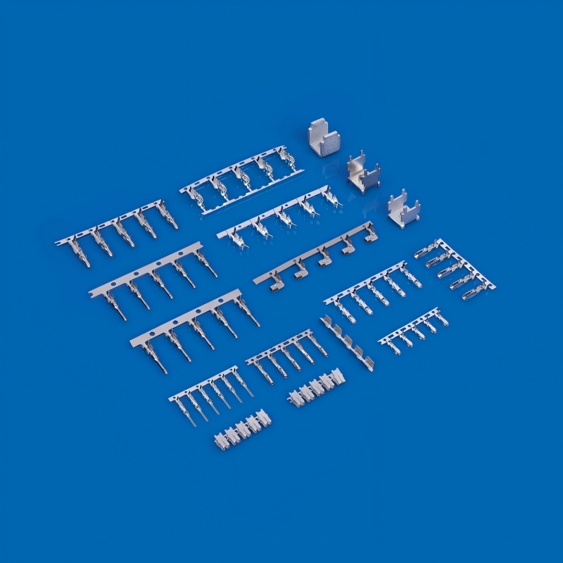
Pick the Right Crimp Terminals for Your Harness
Crimp terminals for wire-to-board and wire-to-wire systems come in many pitches, materials, and current ratings. A typical example is the A2002-TP crimp terminal: a 2.0 mm pitch terminal in phosphor bronze with a tin plating, rated at 3 A and 250 V, and sized for 28 to 22 AWG wire.
When you specify a terminal, send your wire gauge, application, and annual volume to the supplier and ask the engineering team to confirm the right terminal, die set, and tooling before production starts. Most manufacturers support OEM and ODM programs with samples and production quantities. Send your drawing and request a quote.