5 Root Causes of Automotive Connector Failure and How to Test Them
Automotive connector failure almost always traces back to one of five root causes: bad crimps, corrosion, fretting wear, overheating, and failed seals. Each leaves a measurable signature, so each can be caught with the car connector troubleshooting sequence below.
Crimp terminals and housings are high-volume production items for vehicle harness builders, and connector failures are a daily reality for OEMs and their suppliers. Wiring problems top the list of electrical warranty claims, and published analyses put contact faults at roughly 45 percent of all automotive connectors failures.
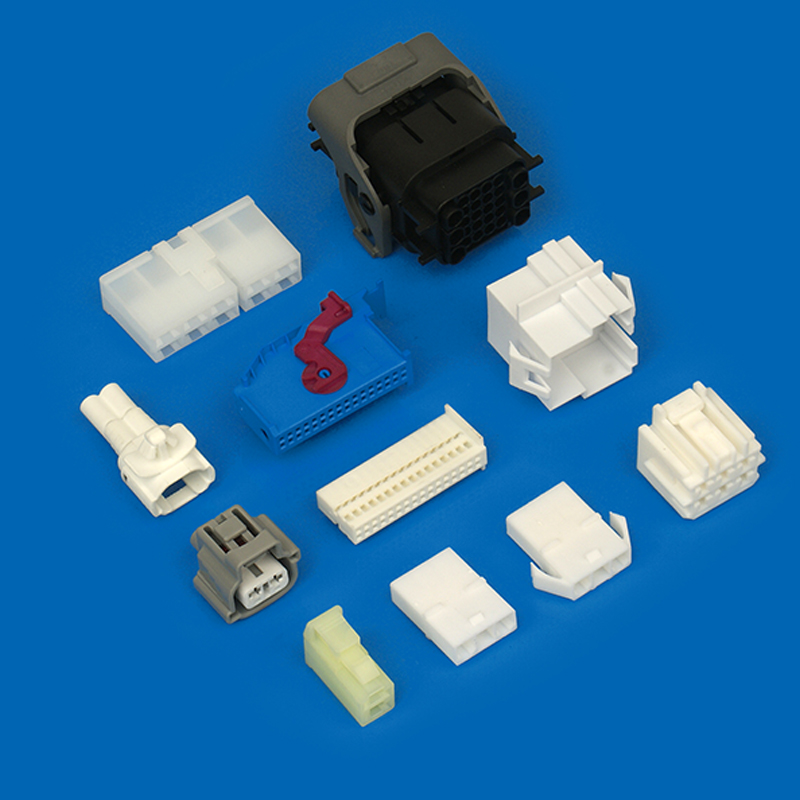
| Root Cause | Failure Signature | Primary Test | Prevention |
|---|---|---|---|
| Terminal push-back (bad crimp) | Intermittent signal, terminal backs out | Crimp height, pull-out force | Correct crimp window, positive lock |
| Corrosion (salt, moisture) | Residue, high resistance, signal loss | Salt spray, damp heat | Plating thickness, sealed housing |
| Fretting corrosion | Resistance climbs under vibration | Vibration plus thermal cycling | Higher contact force, gold for low signals |
| Overheating | Discolored terminals, softened plastic | Millivolt drop test, IR scan | Correct rating, derating |
| Seal failure | Water inside housing, short circuit | Air leak test, IPX7 immersion | IP67 or IP68 housing, seal choice |
Root Cause 1: Terminal Push-Back From Poor Crimping
Push-back happens when a terminal does not stay locked in its cavity, or when the crimp cannot hold the wire. Under vibration the circuit opens, showing up as an intermittent fault on rough roads.
Why Crimp Height Matters
Crimp height is the compressed thickness of the wire barrel around the conductor, and it must sit inside a window set by the terminal spec. Crimp too high and the barrel grips the wire loosely; crimp too low and the strands crush and lose strength. USCAR-21 and IPC/WHMA-A-620 define the window, including the bell mouth and the wire brush.
The window is fixed per wire size. A2002-TP crimp terminals accept 28 to 22 AWG, each with one correct height band.
How to Test Crimp Quality
Three checks cover most crimp problems:
- Measure crimp height with a micrometer against the spec window; drift signals worn tooling.
- Run a pull-out force test on a sample of each lot; a pull below the USCAR-21 minimum points to an undercrimp.
- Microsection a sample and inspect strand deformation under a microscope.
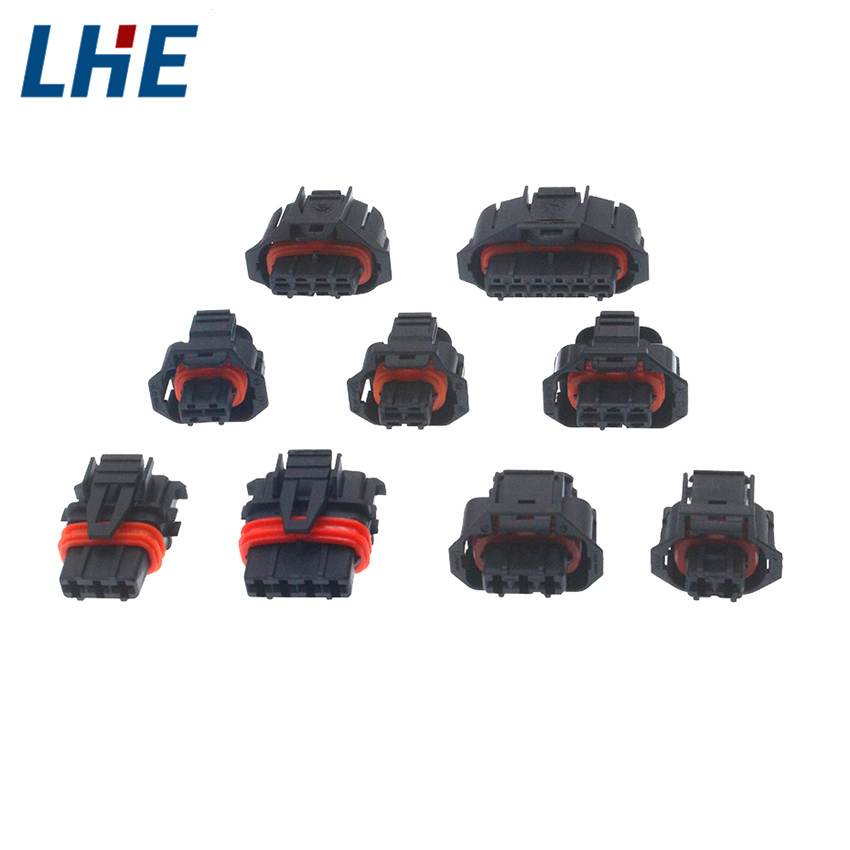
Retention is the second half of push-back. A lance that does not snap into place, or a housing without positive lock features, allows push-back under vibration. That is why positive lock housings such as the 4-pin positive lock housing use a locking beam that seats the terminal and holds it.
Root Cause 2: Corrosion From Salt and Moisture
Corrosion starts where plating stops. Crimp terminals are usually tin plated over phosphor bronze or brass; the thin oxide film on tin breaks locally under contact force. Salt and moisture change that balance: chloride attacks oxide and base metal, and corrosion products grow into the interface.
Plating Failure and Galvanic Attack
Thin or porous plating leaves pinholes where base metal meets the environment. Galvanic corrosion adds a second layer: with salt water present, the less noble of two metals corrodes faster, as between a tin terminal and a copper wire.
Salt Spray and Moisture Testing
Salt spray is the standard screen. ASTM B117 runs a 5 percent sodium chloride fog at 35 °C, with automotive specs typically calling for 48 to 96 hours on assembled connectors. The pass criterion is not appearance but contact resistance after the test.
Damp heat covers the moisture side, holding connectors at high humidity and temperature before retesting. A plating thickness cross-section at incoming inspection confirms the deposit before production.
Root Cause 3: Fretting Corrosion Under Vibration
Fretting corrosion is a wear failure that looks like a contamination failure. Contact surfaces under load move by 10 to 100 micrometers from engine vibration. Each movement scrubs the surface, fresh metal oxidizes, and debris insulates the joint until resistance climbs.
How Fretting Starts
Tin-plated contacts are the most exposed, because tin oxide is a hard insulator and debris stays in the joint. A harness that passed every static check can fail months later on a vehicle that vibrates all day.
Testing for Fretting Corrosion
Fretting is tested by combining its two causes: vibration and temperature change. ISO 16750-3 covers vehicle vibration testing and USCAR-2 the connector sequence. The connector is vibrated across frequency sweeps while contact resistance is monitored, so drift shows up live.
Thermal cycling drives the same micro-movement from differential expansion. Run cycles per ISO 16750-4 and compare resistance before and after; if it creeps upward, the fix is higher contact force or a different plating, usually gold for low-level signals.
Root Cause 4: Overheating From Rising Contact Resistance
Heat in a connector comes from one equation: current squared times resistance. When contact resistance rises, the same current generates more heat, oxidation accelerates, and the loop feeds itself until the terminal discolors or the housing softens.
The Thermal Runaway Loop
Overheating is rarely the original fault; it is the second act of a loose crimp or corroded interface. It belongs on the list because it spreads to adjacent wires and the ECU. The datasheet rating is the first defense: A2002-TP terminals are rated 3 A at 250 V, working range -25 to 105 °C.
Contact Resistance Testing
Contact resistance is measured as a millivolt drop: run a defined test current through the mated connector and read the voltage across the joint (USCAR-21 method). A fresh joint typically reads in the low single-digit milliohm range; what matters is the change after environmental testing.
Thermal imaging gives the field-side version. A harness under load scanned with an IR camera shows hot spots at high-resistance joints, making overheating the easiest failure to find on a vehicle.
Root Cause 5: Seal Failure in Waterproof Housings
A waterproof connector is only as good as its seal, and seals age first. Under-hood temperatures, the silicone gasket and wire seals take a compression set. They stop springing back, sealing force drops, and a connector that passed its IP rating on the bench leaks after two years.
Where Seals Age First
Assembly mistakes do the same damage: a wire seal at the wrong depth, a pinched gasket, or a missing plug turns an IP67 connector into a water path. Water then carries salt in and starts the corrosion failure from root cause two.
Leak and IP Testing
Leak testing finds the problem before water does. The assembled connector is pressurized and pressure decay is measured; a fast decay means a leak path and pinpoints the cavity. On a production line it catches seal defects in seconds.
For validation, immersion is the direct check: IPX7 requires 30 minutes under 1 meter of water, IPX6 tests high-pressure jets. Run thermal cycling first, then immersion, because a seal that fails after temperature aging fails in service too. The A2005-WR waterproof connector series uses sealed 2.0 mm pitch housings for damp environments like outdoor lighting and vehicles.
FAQ: Automotive Connector Failure Questions
Contact-related faults dominate, at roughly 45 percent of connector failures in published analyses. That covers bad crimps, loose retention, and worn surfaces.
Pull the terminal from the cavity with a force gauge and compare it to the USCAR-2 retention minimum. On the crimp side, measure crimp height and run pull-out tests per lot.
A healthy new joint typically reads in the low single-digit milliohm range. Watch the shift after environmental tests: a resistance that doubles after salt spray or thermal cycling is a failed part.
It predicts plating quality, not calendar life. ASTM B117 is an accelerated comparison tool: run two plating options side by side and the better one wins. Pair it with a resistance check after exposure.
Tin is the workhorse for power and general signal circuits. Gold suits low-level signals where contact voltage is too low to break through tin oxide, or where fretting is a known risk. Match the plating to the circuit.
How do I choose a connector supplier that tests before shipping?
Look for a valid UL file, published test data, and traceable material certifications. Ask how they control crimp height and whether they test their own products. Suppliers with an active UL file and documented in-house testing can back their claims.
The five tests in this guide take a connector from unknown to verified: crimp height, pull-out force, salt spray, thermal cycling, contact resistance. When sourcing terminals and housings for a vehicle program, ask for test data and run your own samples. Contact us for test data and samples.