Wire to Board Connectors Guide
Printed circuit boards (PCBs) are common components in modern electronic devices such as smartphones, laptops, medical equipment, and automotive control units. These boards require reliable connections to power sources, sensors, displays, and other peripherals to function effectively.
This is where wire-to-board connectors are used to connect the PCB to external wiring. They provide a direct interface between PCBs and external wiring, ensuring stable signal and power transmission. We will cover circuit board connector types, their applications, how to select the appropriate connector, common challenges, and future trends in the industry.
What is a PCB Connector?
A PCB connector is an electromechanical component that facilitates connections between a printed circuit board and external circuits, including wires, cables, or other boards. Unlike permanent solder joints, these connectors allow for easy disconnection, replacement, or reconfiguration without damaging the PCB.
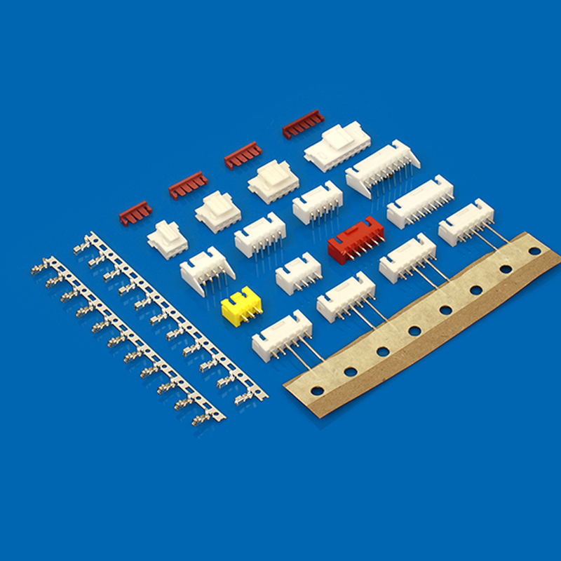
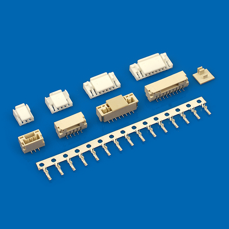
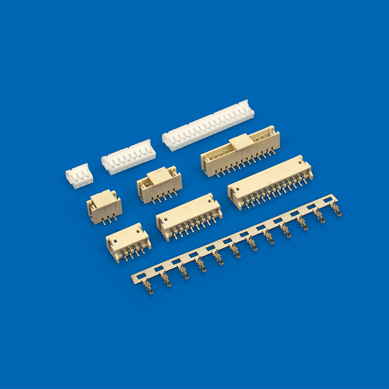
A widely used category is the wire-to-board connector, which establishes a secure link between individual wires and the PCB. They are available in various sizes, pin counts, and locking mechanisms, making them versatile for both consumer and industrial electronics.
Examples include:
- Micro push-to-release wire-to-board connector: Compact connectors that provide easy release mechanisms for maintenance or upgrades.
- Cable to board connector: Facilitates multiple wires bundled in a cable to connect with a PCB.
- Board to cable connectors: Ensure secure board-to-cable integration in automotive, industrial, and communication applications.
- PCB connectors wire to board: General term for connectors that link wires to a circuit board.
These connectors streamline assembly, testing, and servicing, making them a key component in modern electronics.
PCB Connector Types
The following table provides a detailed summary of commonly used pcb board to wire connectors, including expanded descriptions, typical applications, and key features for better understanding.
| Connector Type | Description |
| Pin Headers and Receptacles | Rows of pins soldered to a PCB paired with corresponding receptacles, common in development boards and prototyping |
| Insulation Displacement Connectors (IDC) | Allow wires to connect without stripping insulation, widely used in ribbon cables and high-volume applications |
| Crimp and Poke-In Connectors | Crimped wires attach to terminals before insertion, poke-in connectors provide tool-less connection options |
| Micro Push-to-Release Connectors | Compact connectors with latch mechanisms for easy disconnection and maintenance |
| High-Power Wire-to-Board Connectors | Designed for applications requiring high current capacity and mechanical robustness |
Connector Classification by Application
Wire-to-board connectors are categorized based on their specific industry applications, helping designers choose suitable types for different operational needs.
Consumer Electronics
These connectors are compact and high-density, commonly used in smartphones, laptops, and wearable devices. They support small form factors while maintaining reliable electrical connections.
Automotive Industry
Board to cable connectors in vehicles must handle vibration, temperature fluctuations, and exposure to moisture. They are designed for durability and long-term reliability in critical systems such as engine control and infotainment.
Industrial Applications
Durable cable to board connectors are employed in factory automation, machinery, and control systems. They are built to resist dust, oil, and mechanical stress while providing consistent connectivity.
Medical Devices
High-reliability wire to board connectors are used in patient monitoring, imaging equipment, and laboratory instruments. These connectors ensure safe, precise signal transmission in sensitive environments.
Telecommunications
High-speed circuit board connector types are critical for networking and communication systems, ensuring signal integrity, low latency, and high data throughput.
By selecting connectors according to these specific applications, engineers can enhance device performance, ensure safety, and meet industry standards effectively.
How to Choose the Right Connector?
Electrical Considerations
Choosing a wire-to-board connector starts with understanding its electrical requirements. This involves evaluating the maximum current and voltage the connector can safely handle, as well as maintaining signal integrity in high-speed circuits to prevent data loss or interference.
Mechanical Considerations
Mechanical factors are equally important. Designers need to consider pin spacing, the connector’s durability over repeated mating cycles, and the locking mechanisms that secure connections, ensuring long-term reliability and ease of handling.
Environmental Considerations
Environmental aspects include temperature range, exposure to moisture, dust resistance, and vibration tolerance. The connector must operate reliably under expected conditions to prevent failures in critical systems.
Ease of Assembly
Ease of assembly can greatly affect manufacturing efficiency. Connectors such as micro push-to-release wire-to-board connectors simplify installation and maintenance, reducing labor time and the potential for errors.
Considering electrical, mechanical, and environmental requirements alongside assembly convenience helps ensure that the most suitable pcb board to wire connectors are chosen for each application.
Common Challenges with PCB Connectors and How to Avoid Them
Poor Contact Reliability
One common challenge is poor contact reliability, which can lead to intermittent connectivity or failure. Ensuring the use of high-quality circuit board wire connectors and careful installation techniques can minimize these risks and maintain stable connections over time.
Overheating
Connectors may overheat if not properly matched to their electrical load. Selecting cable to board connectors that meet the power requirements of the system and ensuring adequate heat dissipation can prevent damage and extend connector life.
Space Constraints
Limited space on the PCB can create challenges in placing connectors without interfering with other components. Choosing compact connectors that optimize board layout while maintaining signal integrity helps overcome space limitations.
Mechanical Stress
Repeated mating and unmating, as well as vibration or physical shocks, can stress connectors. Selecting connectors designed for multiple mating cycles and equipped with secure locking mechanisms ensures mechanical reliability and longevity.
Environmental Damage
Exposure to dust, moisture, temperature fluctuations, or corrosive environments can degrade connectors. Using sealed or ruggedized board to cable connectors helps maintain performance under harsh conditions and reduces the risk of environmental failure.
Proactive planning and thoughtful selection of connector types and specifications can significantly improve the overall longevity, reliability, and performance of PCB systems.
Future Trends in PCB Connector Technology
Miniaturization
The demand for smaller micro push-to-release wire-to-board connectors continues to grow, driven by the need for higher pin density in compact electronic devices. Miniaturization allows designers to optimize space on PCBs while still maintaining robust electrical connections, which is particularly important in wearable technology and portable consumer electronics.
Higher Data Rates
Modern electronics require connectors that can handle faster data transfer rates. High-speed pcb connectors wire to board are being developed to support the demands of IoT devices, 5G networks, and AI-driven applications. These connectors maintain signal integrity while minimizing data loss and interference.
Increased Power Handling
As devices become more powerful, connectors need to accommodate higher current capacities. Advanced wire-to-board connectors are designed to handle increased electrical loads without overheating, ensuring reliable operation in both industrial and consumer applications.
Environmental Resistance
Future connectors emphasize durability against environmental stresses. Rugged and sealed board to cable connectors are being developed to withstand extreme temperatures, vibrations, moisture, and dust, particularly in automotive, aerospace, and industrial settings.
Sustainable Materials
Sustainability is becoming a key factor in connector design. Manufacturers are increasingly using eco-friendly plastics and reducing hazardous substances in circuit board wire connectors, aiming to minimize environmental impact while maintaining performance standards.
Integration and Smart Features
Emerging trends also include integrating smart monitoring features into connectors. These features can provide real-time diagnostics, detect connection issues, and help prevent failures, improving maintenance efficiency and system reliability.
These trends collectively influence the development of the next generation of PCB connectors, enhancing performance, durability, and sustainability for a wide range of electronic applications.
Conclusion
Wire to board connectors provide connections in both consumer devices and industrial machinery. They ensure reliable signal and power transmission. Understanding circuit board connector types and their applications helps engineers choose appropriately. As electronics evolve, connectors continue to become smaller, more efficient, and environmentally resistant.